Introduction
Unmanned Aerial Vehicle R based Mission Planning
The uavRmp package is designed
for UAV autonomous mission planning. In the first place it is a simple and open source planning tool for planning survey flights of low budget drones based on R. It provide an easy workflow for planning autonomous
surveys including battery-dependent task splitting and save departures and approaches of each monitoring chunks.
The range of usage of these kinds aof aerial photography is widespread from Digital Surface Models (DSM), Digital Elevation Models (DEM), orthophotos, altitude point clouds to landuse/landscape classification, NDVI forest structure classifications and so on…
Note
WARNING: Take care! There are still a lot of construction zones around. This package is far beyond to be in a mature state. Please implement a double check systems while planning and performing autonomous flight missions. You will have a lot of chances to make a small mistake what may yield in a damage of your UAV or even worse in involving people, animals or non-cash assets.
Check your risk - use parachute systems and, even if everything is running like a charm, keep alert!
Supported UAV platforms
Up to now it has been dedicated to low budget rtf-UAVs as the DJI Phantom (up to P4) series and the Pixhawk flightcontroller family. However the current and future support will focus on Pixhawk based UAVs only.
The open UAV community is focused on the PixHawk autopilot unit and the MissionPlanner or QGroundcontrol software. Both are well documented and provide APIs and easy to use GUIs. Nevertheless they are missing planning capability (APM Planner) or a terrain following autonomous flight planning tool, that is also dealing with battery-dependent task splitting and save departures and approaches (MissionPlanner) yet. Other commmercial competitors like the powerful ugcs software package are still lacking an advanced capability for generating smooth and save surface following flight tasks for low AGL altitudes.
The uavRmd bridges this gap and generates MAVLINK format compliant mission files that can be uploaded to the Pixhawk controller using an integrated function or externally by any Ground Control Station software.
DJI: The reason using DJI UAVs is because of their absolute straightforward usage. Everybody can fly with a DJI but the price for this simplicity is a hermetically closed system. Only the Litchi app provides in addition to a cloud based mission planer an offline/standalone interface to upload a CSV formated way point file for autonomous flights to the Phantom.
PixHawk: The open UAV community is focused on the PixHawk autopilot unit and the Mission Planner software. It is well documented and several APIs are provided. Nevertheless a terrain following autonomous flight planning tool is not available. ‘’‘uavRst’’’ supports the MAVLINK common message format that can be uploaded directly on the Pixhawk controller using Ground Control Station software or for the outdated 3DR Solo use the upload2Solo function.
Installation
The most easiest way to obtain a fairly good runtime enviroment is to setup Linux as a dual boot system or in a VB. For using some of the the Solo related functions you need to install the dronekit python libs in addition.
A full list of necessary libaries and binaries beyond R will soon be provided.
To install from github you need to have installed the devtools package.
devtools::install_github("gisma/uavRmp", ref = "master")
If you want to install all dependencies use:
devtools::install_github("gisma/uavRmp", ref = "master", dependencies = TRUE)
The core planning tools
The core planning tools makeAP (make area plan) and makeTP (make target plan) are creating either intermediate flight control files for the DJI Phantom 3x UAVs or ready to upload control files for the Pixhawk based UAVs like the 3DR Solo. The intermediate DJI control files are expected to be used with the proprietary Litchi flight control app, while the Pixhawk/3DR Solo files are using the MAVLINK common message format.
The basic idea is to provide an easy to use workflow for controlling rtf UAVs on autonomous survey missions.
The types of mission tasks
To define a flight area you have to provide either 4 Points (or 3 lines). You may take more complex vectors like a multi point polygon, but only the first 4 coordinates x1, x2, x3 and x4 (the last one is assumed to be the launching position) are used in exactly this order. If you take a rectangle the 4th corner coordinate will be the launching point. The concept is looking like the following sketch:
x2------x3           x2-------x1
| a                 /
|                  /
|   x4            / x4
|  /             / /
x1/             x3/
This coordinates the length of the line and the angle are used to calculate extend and parallels of the flight plan according to the flight altitude, overlap etc. NOTE: The flight direction depends on the order of the points.
If flightPlanMode = "tracks". The result may look like below.
#--#  #-->              #-----#
|  |  |                /
|  |  |               /
|  |  |              /
|  |  |              #-----#
|  |  |                   /
|  |  |                  /
|  |  |                 /
#  #--#       <--#-----#
If flightPlanMode = "waypoints" Other than using tracks the result is an equal spatial distribution of way points:
#--#  #-->              #--#--#
|  |  |                /
#  #  #               #
|  |  |              /
#  #  #              #--#--#
|  |  |                   /
#  #  #                  #
|  |  |                 /
#  #--#       <--#--#--#
waypoints is optimal for autonomous flights under calm conditions in complex terrain because the camera takes a picture at every way point.
track is optimal for relatively plain areas and automatically triggered picture capturing
NOTE; DJI only: Automatically picture capturing in a time interval works only within the range of the remote control because the UAV needs a trigger signal for taking pictures.
Terrain following task
The argument followSurface = TRUE will switch from fixed AGL flight altitude to a terrain following flight altitude.
NOTE: You have to be aware that by default the UAVs are calibrating the altitude at the launch position in the field! So you need either a correct coordinate altitude or a high resolution DEM to get a good(!) estimation of the launch position and altitude.
You must choose a clearly defined and reliable launching position both in the map and the field. If one fails, we made the experience that the aircraft probably will hit the terrain…
Let us assume a defined flight altitude of 50m. According to the launching point altitude the UAV will act like the following sketch shows:
 x_()_x >>> ............................ UAV started at 30m altitude results in
   ^                                     a "real" flight altitude of 30m + 50m => 80m
   ^               ___60m____
   ^              |          |
   ^      30m _x__|          |
   ^     ____|               |___
 x_()_x_|                        |______

                  ___60m____
x_()_x >>> ......|          |..........  UAV started at 0 m altitude results in
  ^           ___|          |___          "real" flight altitude of 50m above 0m
  ^          |                  |
  ^      ____|                  |
x_()_x _|                       |_______
To avoid negative impacts from the UAV auto-calibration, the launch altitude is used to correct the flight altitude according to:
maximumAltitude_of_surveyArea + altitude_of_launchposition
So the adapted flight altitude is always seen as the flight altitude above the highest terrain altitude:
      x_()_x >>> ..................... real altitude of UAV: 110m
        ^
        ^      ___60m____
        ^     |          |
    _ x_()_x__|   30m    |___
____|                        |
|                            |______
To get a fixed scale flight the launch altitude is used to correct the flight altitude according to:
```maximumAltitude of surveyArea + altitude of launch position```
With the setting of terrainfollowing = true this is calculated for each way point. So the adapted flight altitude looks like:
               ..........
              |          |
          ....|          |....
     ....|     ___60m____    |
....|         |          |   |....... real altitude of UAV: 50m
       30m _x_|          |___
      ____|                  |
  ___|                       |___x___ 0m
Basic mission planning workflow
Overview of the task
This recipe deals with the effective and safe planning of an autonomous flight. This provides basic information about the used hardware and software as well as supplemental data and nice to haves.
Skills you will learn
The basic workflow of planning a good aerial and target oriented flight mission. In the extended version you find some more explanations and hints for improving your planning.
Even if you can assume the use of uavs for autonomous flights as somehow “operational”, you should always keep in mind that avoiding negative impacts is a result of responsible and focused planning.
Please keep in mind that autonomous UAVs can harm the the pilot and environment.
Things you need
- R
- uavRmp package
- Digital Surface Model (DSM) data
- DJI Phantom/Pixhawk UAV
- For DJI only Litchi flight App
- For Pixhawk QGroundcontrol
- Time to work it out
General Workflow
- Identify the area, digitize/type the coords of 3 corners and the launching position
- Adjust the flight parameters to your needs and generate flight control files
- Convert and upload the mission control files either directly to your tablet/smartphone or alternatively via the Litchi cloud.
- Make an extensive preflight check
- Fly the mission
Basic examples
The first example will introduce you to the basic usage and folder structure.
Purpose: Survey flight over flat terrain to generate DSM and orthophoto. It is described for the Phantom 3 and Litchi only.
Addressed issues:
- Create a reliable DSM for near surface retrieval of high resolution pictures
- Create an orthophoto for visual inspection of POIs
The short way
Digitize the 3 corner points of an area you want to map and in addition as fourth point the position of the planned UAV launch. Save it to //firstSurvey.kml//.
   require(uavRmp)
   # get example DEM data
   fn <- system.file("extdata", "mrbiko.tif", package = "uavRmp")
   fa <- system.file("extdata", "flightarea.kml", package = "uavRmp")
   # preset = "uav" suppress all not necessary tools
   vecDraw(mapCenter = c(50.855,8.691),preset="uav")

   # Use the digitized data (assumed to be named "firstSurvey.json")
   # and the example DEM to calculate a flight control file
   fp <- makeAP(surveyArea = fa,
                demFn = fn)
NOTE: The first two points determine the flight angle and direction the second and third coordinate determine the width of the area.
If you want so save it on your SD card, open the Litchi Mission website and click on the button Missions->Import. Next navigate to the control file firstsurvey_1001.csv (you’ll find it in the folder projectDir/mission/date/control). For exporting it choose Missions->Save and navigate/upload it to your missions subfolder of the Litchi app. That’s it.
Even more simple is the option to connect with the litchi cloud. While you are logged in with the same account it is synchronizing the data as soon as you start the litchi app.
The long way
Digitizing the survey area
Build in vecDraw function
We want to plan a flight in a more or less flat terrain in the upper Lahn-valley. First load the libraries and next start the small digitizing tool that is provided in ‘‘uavRmp’’.
You may take any other tool to digitize the survey area as well as you may type the coordinates on Stdin.
 # load uavRmp
 require(uavRmp)

 # start digitizing tool with preset = "uav" for a reduced toolbar
 # see ?leafDraw for more information
 vecDraw(mapCenter = c(50.855,8.691),preset="uav")

Feel free to digitize - similar to the above figure - the four points needed:
- P1, P2, P3 define the extend and angles of the mission area.
- P1 is the starting point of the survey
- Flight direction angle and along distance is defined by P1->P2
- P2->P3 defines the cross distance
- P4 is the launching point. Try to digitize it very carefully because of getting an optimal launch altitude.
For an optimal deliniation of the flight area, please keep in mind some hints:
- It makes sense to put the launching position somewhere near or within the proposed survey area with respect to an optimal visibility to the UAV and the shortest possible distance for the radio controller to keep in contact with the UAV.
- It is helpful to fly along structures with necessary climbs at the end of each track. It saves energy and in most cases the climbs can be controlled easier.
- Try to identify your launching point ** very carefully** and ** most reliable**. The UAV is taking this position as a home (reference) point for both position and altitude.
Finish digitizing and save it as a KML file. Take care to add the correct extensions ‘’.kml’’ (the ‘‘makeAP()’’ function is requiring the correct extension). In the current example save it as a kml file named ‘‘firstSurvey.kml’’.
Calling makeAP
Working directories and other structural defaults
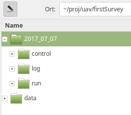
There are a lot of optional arguments available that helps to control the generation of an autonomous flight plan. In this first use case we keep it as simple as possible. First we will focus the arguments to organize the project. All results will be stored in a fixed folder structure. The root folder is set by the argument projectDir. e.g. ‘’/proj/uav’’. The current working directory will then be generated from the /proj/uav/firstsurvey’’. According to the date of planning the following subfolder structure is set up. For the mission control files a folder named ‘‘control’’ is used, the log files are saved in the locationName and is always a subfolder of the ‘‘projectDir’’. So in this case it is set to ‘‘firstSurvey’’. The resulting folder for a specified location in a speciefied project is then ‘’log folder the temporary data sets are stored in a folder called ‘‘run’’.
PLEASE NOTE: Optionally all used data files are copied to a folder called ‘‘data’’, which is located directly under the ‘‘projectDir’’ folder.
The project structure will look like the figure.
The used arguments
‘‘flightAltitude’’ is set to the (legal) maximum of 100m, ‘‘flightPlanMode’’ is set to ‘‘track’’ and finally a DEM of this area with 20m resulution is used to retrieve the altitude of the launching point. If we use the example data we first have to convert them to a valid GeoTiff file.
  # get example DEM data
 fn <- system.file("extdata", "mrbiko.tif", package = "uavRmp")
 fa <- system.file("extdata", "flightarea.kml", package = "uavRmp")

 fp<-makeAP(surveyArea=fa,
            maxSpeed =35,
            demFn = fn)
The script generates:
- R objects for visualisation
- log file
- flight control file(s).
All three of them are important even if a quick inspection of the generated objects is most of the time sufficient. The log file dumps the all important parameters of the calculated mission. Most important the calculated mission speed and picture rate based on an estimation of the mission time.
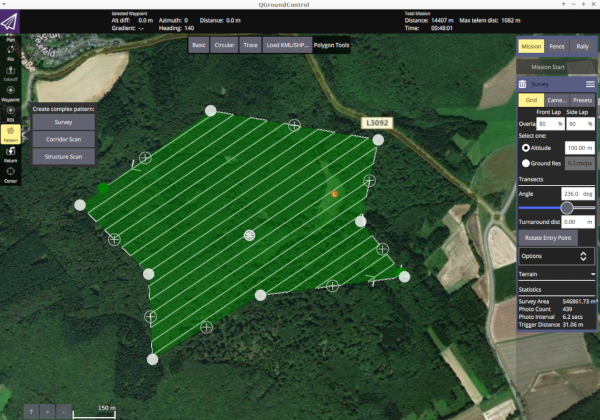
Using the mapview package you can easily visualize the results. The below example shows the footprints of the images (blue), surveyArea (red), turnpoints of track (blue circles) and the launch position (red).
 require(mapview)
 mapview(fp[[5]],color="red", alpha.regions =0.1,lwd=0.5)+
 mapview(fp[[1]],lwd=1,cex=4)+
 mapview(fp[[3]],color="red",cex=5)+
 mapview(fp[[4]],color="darkblue", alpha.regions =0.1,lwd=0.5)